Hoa Wiring Ladder Diagram

Dol Starter Panel Wiring Diagram Save Start Stop And Motor

Seb03 Puissance Moteur Jpg 1420 984 Electrical Circuit Diagram

Electric Heat Strip Wiring Diagram Di 2020 Diagram

7 Memory Of A Plc Data And Program Files Youtube With Images

Unique Blueprint Electrical Symbols Diagram Wiringdiagram

Automotive Wiring Diagram Isuzu Wiring Diagram For Isuzu Npr
The top rung is read from left to right.
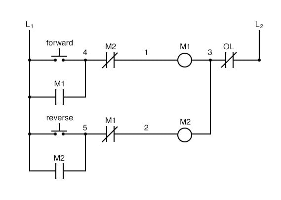
Hoa wiring ladder diagram. The circuit shown in figure 27 1 permits a motor to be operated by a float switch or to be run manually. Wiring diagrams 55 57 type s ac combination magnetic starters 58 59 class 8538 and 8539 58 59 3 phase size 0 5 58. Power is supplied by connecting a step down transformer to the control electronics by connecting to phases l2 and l3. Each rung on the ladder defines one operation in the control process.
The lower voltage is then used to supply power to the left and right rails of the ladder below. A ladder diagram is read from left to right and from top to bottom. We can redraw this diagram in a different way using two vertical lines to represent the input power rails and stringing the rest of the circuit between them. Hand off automatic controls are used to permit an operator to select between automatic or manual operation of a motor.
This is a graphical language showing the logical relationships between inputs and outputs as though they were contacts and coils in a hard wired electromechanical relay circuit. The switch is shown as a single pole. Upgrading a machine to plc control may seem like a daunting task. Then the second rung down is read from left to right and so on.
We ll discuss the devices that make up a hand off auto circuit and how. In this lesson we ll examine a common industrial application of 2 wire control circuits known as a hand off auto circuit. This video walks you through the basic 2 wire and 3 wire control for 3 phase motor controllers. Hand off automatic controls recognize hand off automatic switches on a schematic diagram.
The contacts m will be controlled by the coil m the output of the motor starter goes to a three phase ac motor. Wiring diagram book a1 15 b1 b2 16 18 b3 a2 b1 b3 15 supply voltage 16 18 l m h 2 levels b2 l1 f u 1 460 v f u 2 l2 l3 gnd h1 h3 h2 h4 f u 3 x1a f u 4 f u 5 x2a r power on optional x1 x2115 v. However if you take your time and learn how to convert a basic wiring diagram to a ladder logic plc program it can be an easily achievable task. The wiring diagrams heavy lines.
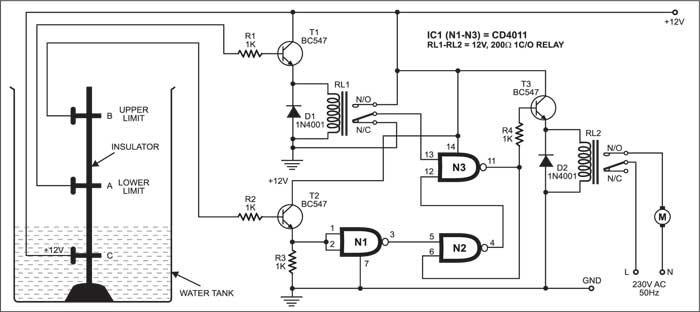
A wiring diagram gives the necessary information for actually wiring up a group of control devices or for physically tracing wires when trouble shooting is necessary. Figure 1 a motor controller schematic. The most common language used to program plcs is ladder diagram ld also known as relay ladder logic rll. The diagram shows the circuit for switching on or off an electric motor.
The figure shows the scanning motion employed by the plc.

Wiring Riddle No 3 Auto Transfer Switching Control Diagram

New 2004 Dodge Ram 1500 Ignition Wiring Diagram Diagram

Star Delta Starter Control Wiring Electrical Circuit Diagram
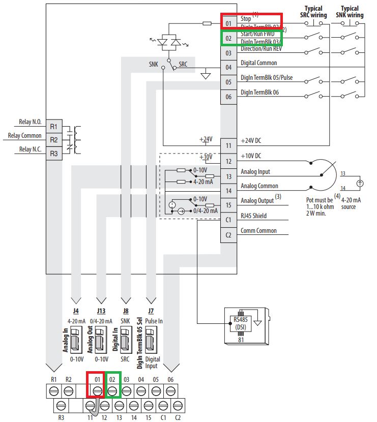
Powerflex 525 Vfd Setup Programming Parameters Wiring Diagram

Honeywell Boiler Zone Valves Wiring Wiring 3 Zone With Honeywell

Unique Wiring Diagram Air Conditioning Compressor With Images

Wiring Diagram Craftsman Riding Lawn Mower I Need One For

Folded Dipole Fed With Tv Cable Post 1749 With Images Ham

Wiring Diagram For 1998 Chevy Silverado Google Search 1998

Micro820 Plc Wiring Diagram With Images Diagram Electrical

Rev For Three Phase Motor Connection Power And Control Diagrams
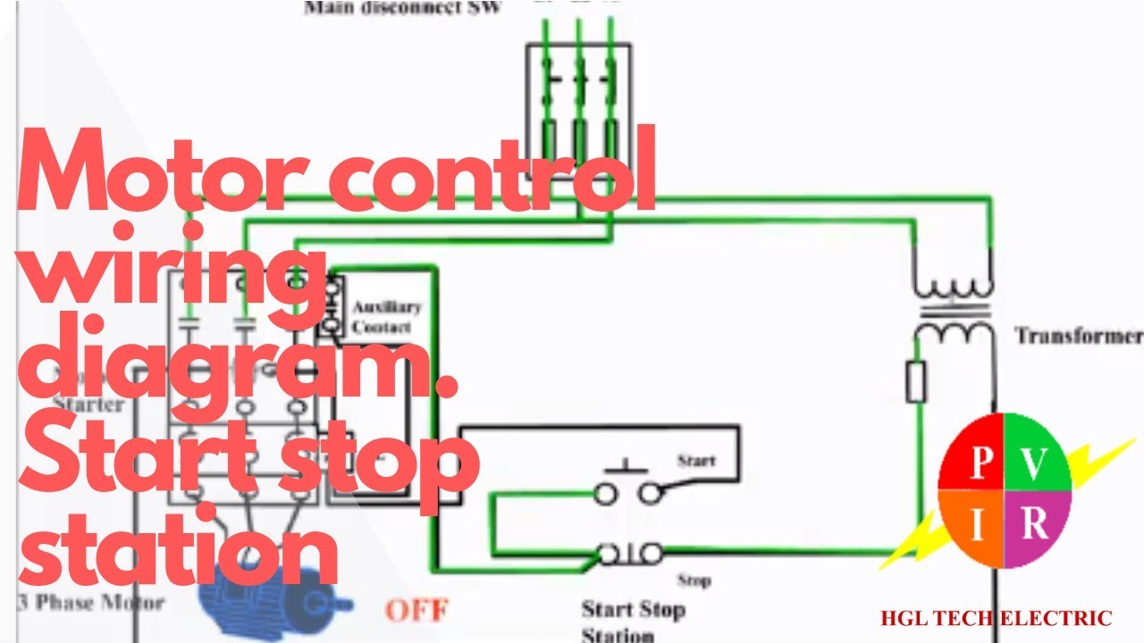
Motor Control Start Stop Station Motor Control Wiring Diagram

Rotork Wiring Diagrams